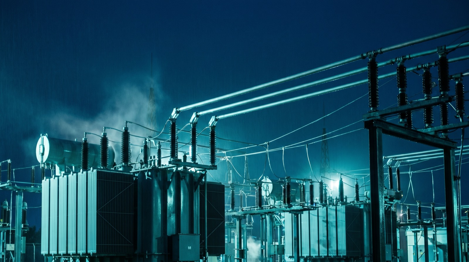
Interconnection is where well-designed projects go to die. A technically sound array or storage system can be rendered uneconomic by an interconnection study that returns tens of millions in network upgrade costs, or stalled for years in a congested queue. Our practice front-loads that risk: before a dollar of capital is committed, we model the point of connection against published hosting-capacity maps, feeder loading, and the protection scheme to estimate the study tier and likely upgrade exposure.
Hosting capacity and MW headroom
Every feeder has a finite capacity to absorb distributed generation before voltage, thermal, or protection limits are breached. We quantify the available MW headroom at the candidate point of connection using utility hosting-capacity data and our own power-flow modeling, identifying whether a project fits within existing headroom or triggers reconductoring, transformer upgrades, or substation work. Where headroom is tight, we evaluate inverter power-factor control, active voltage regulation, and storage to keep the injection within limits and avoid upgrade triggers.
Voltage rise is the binding constraint on most distribution-connected projects. We design to keep steady-state voltage rise under five percent at the point of connection, using reactive power control and, where necessary, curtailment logic that sacrifices a small fraction of annual energy to preserve the connection without network reinforcement.
- Hosting-capacity and power-flow analysis at the point of connection
- Protection coordination and anti-islanding per IEEE 1547
- Reactive power and volt-VAR control to manage voltage rise
- Marginal loss factor modeling for revenue-grade yield forecasts
- Queue-position strategy and study-tier risk assessment
Protection and standards compliance
Interconnected generation must protect both the asset and the network. We design protection schemes compliant with IEEE 1547 and applicable local standards, covering anti-islanding, voltage and frequency ride-through, and fault contribution coordination with upstream relays. Smart-inverter functions are configured to the utility's required settings so the project supports, rather than degrades, grid stability during disturbances.
Loss factors and revenue modeling
Energy injected at the connection point is not the energy that earns revenue at the trading node. Marginal loss factors, which can range roughly from 0.92 to 1.08 depending on the asset's electrical location relative to load centers, scale every megawatt-hour up or down before settlement. We incorporate the applicable loss factor into yield and revenue forecasts from the outset, because a project sited in a high-loss pocket of the network can lose several percent of its gross revenue invisibly. Factoring it early changes siting decisions and protects the financial model.
We also track queue dynamics. Reform of interconnection queues toward cluster studies and readiness deposits has changed the strategic calculus; we advise on filing timing, project staging, and withdrawal options to keep a viable queue position without stranding capital in a study that may return prohibitive costs.