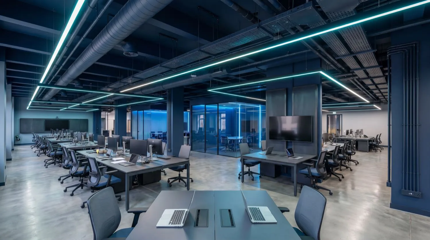
Commercial electrical engineering is governed by a more demanding set of design variables than residential work. Prospective short-circuit currents at commercial switchboards routinely reach 10–25kA, fault ratings must be verified against network data from the distribution network service provider, and sub-mains conductors must be sized under AS/NZS 3008.1.1 using both thermal and voltage-drop criteria simultaneously. Nexus Grid Electrical engineers every commercial project from load analysis through to final AS/NZS 3017 test and inspection, ensuring each installation is documented, compliant, and maintainable.
Maximum Demand Calculations and Load Analysis
AS/NZS 3000:2018 Section 2 sets out the framework for maximum demand assessment, and commercial installations demand rigorous application of that framework. A 2,000m² open-plan office carrying general power, data floor boxes, lighting, a commercial kitchen, and a central plant room cannot be sized on area-based rules of thumb. Nexus Grid engineers compile a room-by-room load schedule, apply diversity factors per AS/NZS 3000 Appendix C, and calculate the verified maximum demand that drives every upstream conductor and protective device selection.
Three-phase supply from the network arrives at 400V line-to-line and 230V line-to-neutral. Phase balancing is a critical design step in commercial distribution — unequal loading creates neutral current in shared MEN conductors, increases transformer losses, and can trigger neutral overcurrent in legacy switchboards. Our load schedules present phase allocation across all final sub-circuits to maintain imbalance below 10% of full-load current on each phase.
Sub-Mains Design and Busbar Sizing
Sub-mains are the arterial conductors linking the main switchboard to distribution boards throughout a tenancy or building. AS/NZS 3008.1.1 Table 6 provides the cable current-carrying capacity data, corrected for installation method, grouping, and ambient temperature. Nexus Grid engineers apply derating factors rigorously — cables routed in a common cable tray alongside other loaded conductors can derate to 60–70% of their open-air rating, making ungrouped or oversized conductors a common and costly defect in commercial fit-outs.
- Sub-mains sized per AS/NZS 3008.1.1 with thermal and voltage-drop criteria applied concurrently
- Voltage drop verified at ≤5% from point of supply to most remote load per AS/NZS 3000 Clause 3.6
- Copper busbar sizing calculated at maximum operating temperature (75°C for PVC, 90°C for XLPE)
- Fault-rated switchboards per AS/NZS 61439-1 and -2, with kA rating matched to network prospective fault current
- Type B, C, and D circuit breaker curves specified to suit load characteristics — motor, lighting, or resistive
- RCD protection on all socket-outlet circuits per AS/NZS 3000:2018 Clause 2.6
Switchboard Engineering and AS/NZS 61439 Compliance
Commercial switchboards assembled to AS/NZS 61439-1 (general requirements) and AS/NZS 61439-2 (power switchgear and controlgear assemblies) carry verified fault ratings, defined internal segregation forms, and documented short-circuit withstand capability. Where network fault levels are uncertain, our engineers request a network fault level certificate from the DNSP and verify the selected main switch and downstream devices are rated accordingly. A 25kA fault rating is typical for commercial supplies in suburban Queensland; inner-city high-rise premises may present 40kA or higher, requiring purpose-built assemblies.
Sub-distribution boards within tenancies are designed to AS/NZS 61439-3 (distribution boards for household and similar use) or -2 depending on complexity. Every board leaves the factory with a completed Form of Conformity and test report, and Nexus Grid engineers verify that installed boards match the verified design schedule before energisation. Metering provisions — including sub-metering for individual tenancies — are incorporated at the design stage, not retrofitted.
Power Factor Correction and Energy Metering
Commercial sites with significant inductive load — air conditioning compressors, lift motors, large UPS systems — typically exhibit power factors in the 0.75–0.85 range without correction. Network tariffs for commercial customers frequently include a reactive energy component or a low-power-factor penalty above contracted kVA. Nexus Grid engineers assess the reactive load profile, specify automatic power factor correction (APFC) capacitor banks to bring power factor above 0.95 lagging, and confirm that capacitor bank switching does not introduce harmful harmonic resonance with variable speed drives already present on site. Total harmonic distortion (THD) analysis is conducted where VSD loading exceeds 20% of transformer kVA.