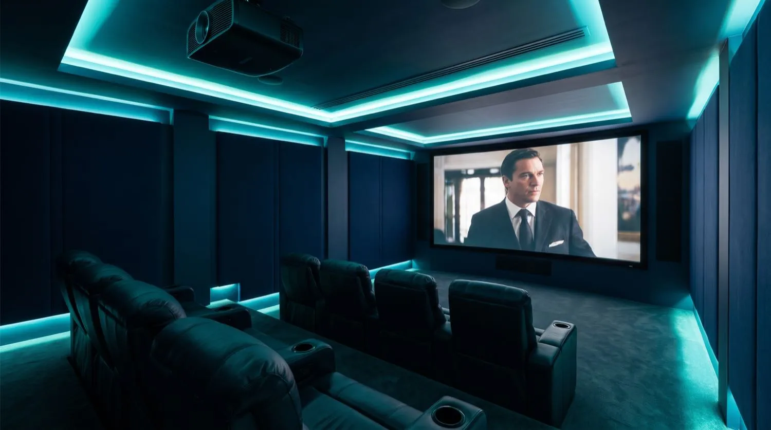
The electrical infrastructure underpinning a home theatre is specialised engineering work distinct from general residential wiring. Shared circuits introduce conducted noise from refrigerator compressors, HVAC motors, and dimmer harmonics that manifest as audible hum, digital signal degradation, and premature failure of sensitive AV components. Nexus Grid approaches every home theatre project with a dedicated circuit design strategy, treating the theatre as an isolated electrical zone with its own protection, earthing, and power conditioning architecture.
Dedicated Circuit Design and Maximum Demand
A reference-grade home theatre system — comprising a 4K laser projector, AV receiver, multi-channel amplifiers, a projection screen motor, and bass management subwoofers — can present a total connected load of 3,000–5,000W at full output. Nexus Grid engineers calculate the maximum demand for the AV rack using manufacturer power draw specifications and applies AS/NZS 3000:2018 demand factors to determine mains cable sizing. A minimum of two dedicated 20A circuits is specified for the equipment rack: one for high-current amplification and another for source equipment and processors, segregating noisy switching power supplies from sensitive preamplifier and DAC stages.
Voltage drop is held to ≤3% on dedicated AV circuits — tighter than the 5% AS/NZS 3000:2018 ceiling — because supply voltage variation directly affects linear power supply regulation in high-end audio equipment. Conductor sizing is calculated using AS/NZS 3008.1.1 impedance tables at the full-load current of the circuit.
Earthing, Equipotential Bonding, and Ground Loops
Ground loops are the most common source of hum and interference in multi-component AV systems. They arise when signal-reference earth paths through RCA, XLR, or HDMI interconnects create circulating currents due to potential differences between equipment chassis. The engineering solution is strict equipotential bonding — all AV rack equipment shares a single-point earth connection at the rack earth bar, which connects to the installation MEN point via a dedicated earth conductor. This star-earth topology eliminates circulating earth currents without compromising AS/NZS 3000:2018 safety earthing requirements.
- Dedicated star-point earth bar at AV rack with single bond to installation earth per AS/NZS 3000 Clause 5
- Separated circuit neutrals — AV circuits isolated from shared neutral bars carrying dimmer and motor loads
- Projector circuit on dedicated 15A or 20A run with conductor sized for ≤3% voltage drop at rated lamp current
- Rack power distribution unit (PDU) with Type 3 SPD on individual outlets — coordinated with Type 2 SPD at switchboard
- Separate conduit routes for mains-voltage and low-voltage/signal cabling throughout wall and ceiling voids
- All conduit bends and draw-in points documented for future cable additions without invasive work
Structured Low-Voltage and Signal Cabling
Low-voltage cabling in a home theatre encompasses HDMI 2.1 (48Gbps bandwidth for 8K/120Hz), Cat6A data runs for IP-controlled components, RS-232 serial for legacy device control, 12V trigger cables for automated screen and projection lift actuation, and speaker cables sized for amplifier output impedance and room run length. All low-voltage cabling is installed in dedicated conduit or cable tray, separated from mains wiring by the minimum 50mm clearance required by AS/NZS 3000:2018 Wiring Rules to prevent electromagnetic interference.
Speaker cable cross-section is specified based on amplifier output impedance (typically 4–8 ohms nominal) and run length to maintain total cable resistance below 5% of nominal speaker impedance — a threshold above which damping factor degradation becomes audible. For a 4-ohm nominal speaker on a 12-metre run, this dictates 4mm² minimum speaker cable.
Surge Protection and Power Conditioning
AV equipment contains dense switching-mode and linear power supply infrastructure sensitive to transient overvoltages well below the ≥4kV impulse levels that damage domestic appliances. Nexus Grid specifies a coordinated two-tier surge protection strategy: a Type 2 SPD at the main switchboard (AS/NZS 1768 compliant, ≥20kA impulse current rated) clamping distribution-network transients, and a Type 3 SPD integrated into the rack PDU providing point-of-use clamping to ≤500V peak for equipment protection. The two tiers are coordinated by voltage protection level (Up) and SPD separation distance to ensure effective energy sharing between devices.