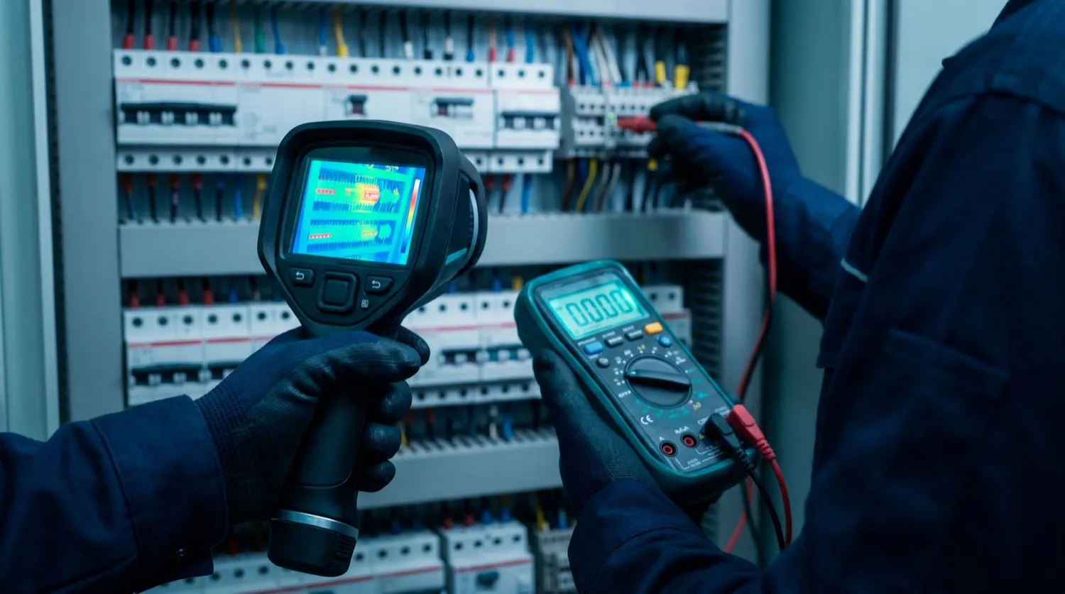
Recurring faults in electrical installations — circuit breakers that trip under normal load, RCD safety switches that activate without an obvious cause, warm switchboard enclosures, or unexpectedly high energy consumption — are rarely random. They are symptoms of a specific, locatable defect. Nexus Grid Electrical applies the systematic diagnostic methodology defined in AS/NZS 3017 (Electrical Installations — Verification Guidelines) to identify the root cause of any fault with precision, eliminating the cost and disruption of speculative component replacement.
Why Intermittent Faults Are Particularly Dangerous
A fault that clears itself — such as a high-resistance joint that cools between load cycles, or insulation that tracks to earth only when wet — is often more dangerous than a fault that is consistently present. Intermittent conditions can persist for months, steadily degrading insulation, generating heat, and increasing the risk of a catastrophic failure. Our diagnostic process specifically targets intermittent faults through load-cycle testing, thermal imaging under operating conditions, and insulation resistance trending over time.
- High-resistance connection detection: joint temperatures exceeding 10 °C above ambient are flagged as defective
- Insulation resistance (IR) measurement per AS/NZS 3017: pass criterion ≥ 1 MΩ at 500 V dc test voltage for low-voltage circuits
- Earth fault loop impedance (Zs) measurement to verify protective device disconnection times per AS/NZS 3000:2018 Table 8.1
- Prospective fault current (PFC) assessment at the origin of each distribution board to confirm switchgear breaking capacity
- Continuity testing of all protective conductors (PE) and main earthing terminals
- Polarity verification to confirm active, neutral, and earth conductors are correctly terminated throughout the installation
Thermal Imaging for Electrical Installations
Thermal (infra-red) imaging is the most effective non-invasive technique for identifying resistance heating in electrical systems. A loaded conductor with a loose termination, a corroded busbar connection, or an overloaded circuit breaker will exhibit an elevated surface temperature that is invisible to the naked eye but clearly resolved on a calibrated infra-red camera. Nexus Grid Electrical uses IEC 62053-class thermal cameras to survey switchboards, distribution panels, motor control centres, and cable trays under full operating load. Results are cross-referenced with measured current values to produce a severity rating aligned to the Australian Institute of Non-Destructive Testing (AINDT) temperature differential classification: Category 1 (1–10 °C above reference, monitor), Category 2 (10–40 °C, investigate), Category 3 (>40 °C, immediate action).
RCD Nuisance Tripping Analysis
Residual current devices (RCDs) are mandated under AS/NZS 3000:2018 clause 2.6 for socket outlet circuits and certain fixed wiring applications. An RCD that trips repeatedly under normal operating conditions is not faulty — it is detecting a genuine earth leakage current that summed across all connected loads exceeds the 30 mA threshold. Identifying the source requires methodical half-split circuit isolation to pinpoint which branch, sub-circuit, or individual appliance is generating the leakage. Common causes include deteriorated cable insulation on aged wiring, moisture ingress into outdoor fittings, degraded motor windings in appliances, and accumulated leakage from a large number of switch-mode power supplies sharing one RCD-protected circuit.
- RCD trip-time verification: all tested RCDs must disconnect within 300 ms at rated tripping current (30 mA) per AS/NZS 3000:2018
- Earth leakage current measurement across individual sub-circuits to isolate leakage contributors
- Insulation resistance trending: repeat measurements at 28-day intervals to track degradation rate in aged wiring
- Half-split isolation method to locate fault zone without complete installation shut-down
- Load flow analysis using power quality analyser to detect harmonic distortion contributing to neutral conductor overloading
Diagnostic Reporting and Remediation Planning
Every fault-finding engagement concludes with a written Electrical Inspection and Test Report structured in accordance with AS/NZS 3017 Appendix A. The report records all instrument readings, identifies each defect with photographic evidence, classifies severity, and recommends remediation works in priority order. For larger installations, we provide a multi-year maintenance schedule that aligns future testing intervals with the risk profile of the installation. This documentation supports insurance claims, due diligence processes for property transactions, and regulatory audit by the relevant state electrical safety regulator.