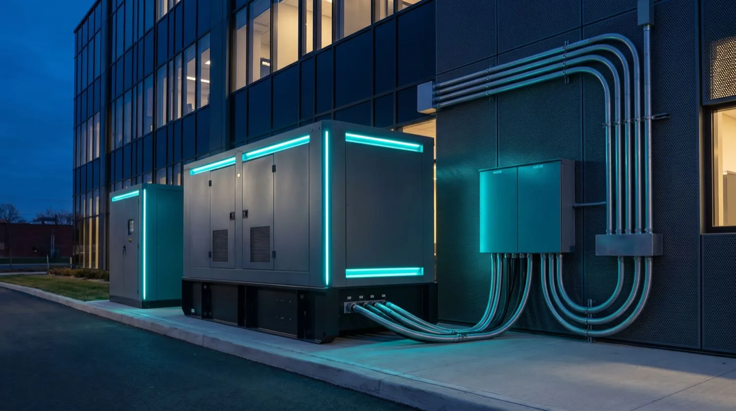
Power supply interruptions cost Australian businesses an estimated hundreds of millions of dollars annually in lost production, spoiled stock, equipment damage and data loss. For critical facilities — hospitals, data centres, water treatment plants, cold-chain logistics facilities — an unplanned outage lasting more than seconds is unacceptable. Nexus Grid Electrical engineers standby power solutions from the load analysis stage through to final acceptance testing, applying AS/NZS 3010 (Electrical Installations — Supply from Generating Sets) as the primary technical standard and coordinating protection device settings to ensure safe, automatic changeover without nuisance tripping or back-feed into the distribution network.
Load Analysis and Generator Sizing
Generator sizing begins with a detailed critical load schedule — not a rough estimate based on main switchboard rating, which would result in a significantly oversized, inefficient plant. Nexus Grid engineers categorise loads into essential (must run on standby), non-essential (shed during standby) and deferred-start (allowed a staged restart sequence). From this schedule, we calculate the total standby kVA requirement accounting for the power factor of the load mix — motor loads presenting a lagging power factor of 0.8 or lower are the design-governing condition, as generator alternator rating is expressed in kVA at 0.8 power factor lagging per AS/NZS 3010 and ISO 8528.
Motor starting imposes a transient current demand — typically five to seven times full-load current for direct-on-line starts — that causes a momentary voltage dip on the generator bus. Where the load schedule includes large motors, Nexus Grid engineers model the step-load transient to ensure the generator's transient voltage regulation (TVR) keeps the bus voltage above 85% of nominal during the worst-case starting sequence. Soft-starters and variable speed drives reduce starting kVA demand significantly and are specified where the generator sizing is otherwise impractical.
Automatic Transfer Switch Design and Changeover Coordination
The automatic transfer switch (ATS) is the functional heart of any standby power system. AS/NZS 3010 and AS/NZS 3000 Clause 4.9 together require that the changeover arrangement physically prevents simultaneous connection of the generator and the network supply to any load — a requirement that rules out simple contactor-based schemes without mechanical or electrical interlocking. Nexus Grid specifies three-position (Normal-Off-Emergency) motorised switchgear with dual mechanical and electrical interlocks, or dedicated ATS controllers with integrated logic, depending on application.
The ATS logic sequence under AS/NZS 3010 commences when the supply voltage drops below the generator controller's set threshold — typically 85% of nominal for longer than a configurable dropout delay (commonly 3–5 seconds to ride through momentary dips). The generator starts, reaches rated voltage and frequency within 10–15 seconds for most diesel sets, and the ATS transfers the essential load bus. On restoration of mains supply, the ATS holds on generator for a retransfer delay — typically 3–10 minutes — to confirm mains stability before transferring back, running the generator on no-load for a cool-down period before shutdown.
AS/NZS 3010 Installation Requirements and Protection Coordination
- Critical load schedule with essential / non-essential / deferred-start categorisation
- Generator kVA sizing at 0.8 power factor lagging per AS/NZS 3010 and ISO 8528
- Motor starting transient analysis — TVR model for worst-case step-load sequence
- ATS with mechanical and electrical mains/generator interlocking per AS/NZS 3010 Clause 4
- Changeover transfer time target ≤10 seconds for essential loads, ≤60 seconds for non-essential
- Earthing system design — TN-S generator neutral earthing and MEN coordination per AS/NZS 3000
- Protection relay coordination — generator overcurrent, reverse power and loss-of-mains settings
- Weekly auto-exercise run programming and monthly full-load test scheduling
- AS/NZS 3017 commissioning test and AS/NZS 3010 Certificate of Compliance at handover
Fuel Systems, Enclosures and Ongoing Maintenance
Generator installation extends beyond the electrical scope. Nexus Grid coordinates with mechanical contractors on diesel fuel system design — base-tank sizing for 24- or 72-hour runtime autonomy, fuel polishing circuits to prevent microbial growth in long-term stored fuel, and day-tank level controls where the generator is remote from the primary storage tank. Acoustic enclosure selection is informed by the site's noise-impact requirements under local council planning conditions, with typical open-set generator noise of 95–105 dB(A) at 1 metre reduced to 65–75 dB(A) at 1 metre by an engineered acoustic canopy.
Post-installation, Nexus Grid provides structured maintenance programs covering monthly visual inspection and auto-start test, quarterly no-load run with voltage and frequency verification, and annual full-load test against the critical load bus. Load bank testing — applying a calibrated resistive load equal to the generator's rated kVA — is performed to verify alternator and engine performance at nameplate output, identifying engine de-rating issues or voltage regulator faults before a real power outage demands the system's full capability. All maintenance records are retained in a site-based generator log book in the format recommended under AS/NZS 3010.