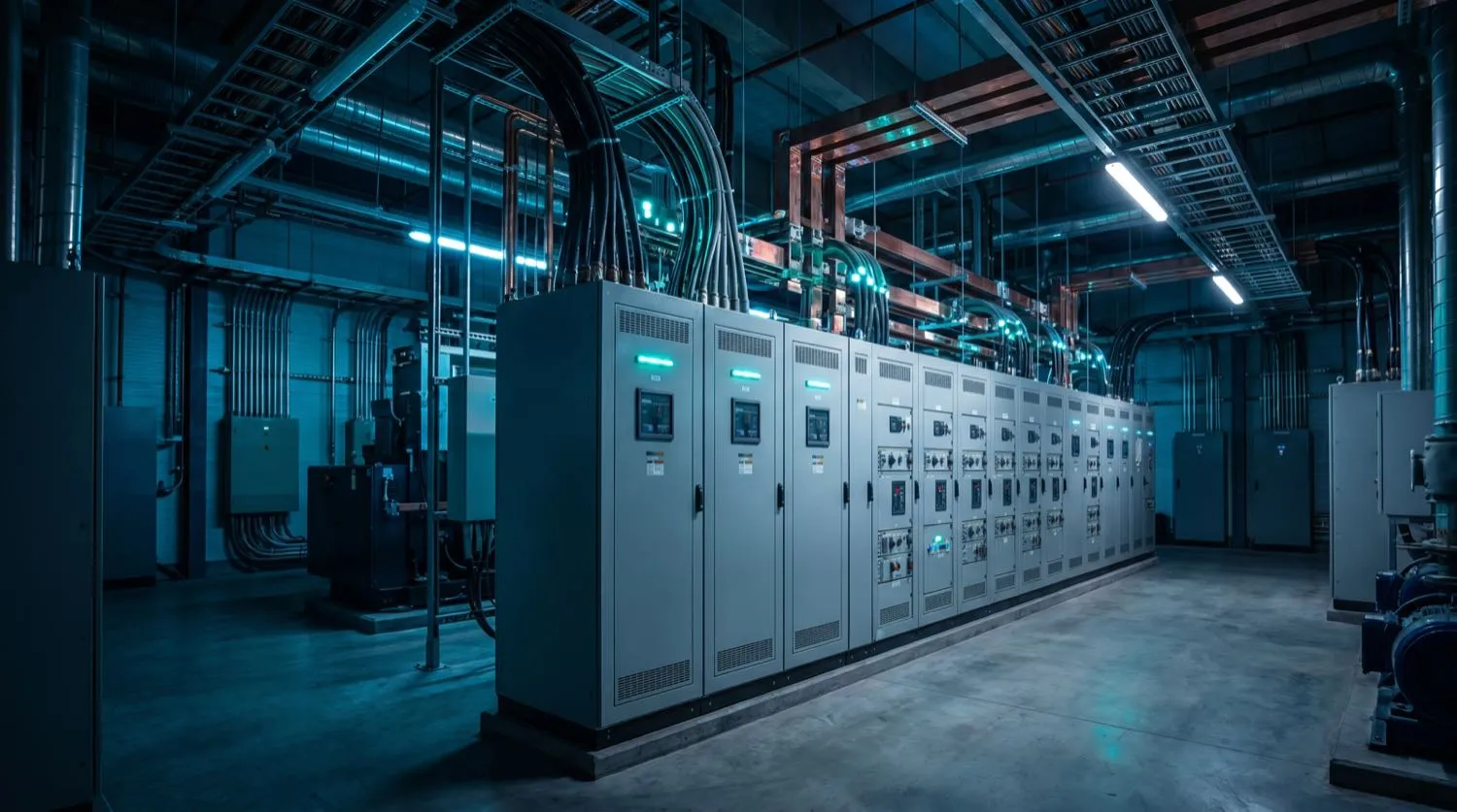
Industrial electrical systems operate at fault levels, conductor currents, and mechanical complexity that demand engineering discipline well beyond commercial practice. Motor control centres handling hundreds of amperes of inductive load, PLC control wiring running alongside high-voltage power cables, and machinery earthing bonded to structural steel under AS/NZS 3000 Part 5 — each element must be engineered as part of a coherent system, not assembled in isolation. Nexus Grid Electrical brings a systematic engineering approach to industrial sites, working from maximum demand and fault level analysis through to commissioning and AS/NZS 3017 test certification.
Motor Control Centres and Protection Coordination
Motor control centres (MCCs) are the nerve centres of industrial electrical systems. A correctly engineered MCC for a Queensland manufacturing facility might carry twenty-four motor feeders ranging from 0.75kW general-purpose units through to 75kW compressor motors, alongside PLC control supplies, instrument transformers, and metering circuits. AS/NZS 61439-2 governs the assembly and verification of MCC panels, requiring documented short-circuit withstand testing, defined segregation form (Form 3b or Form 4b for industrial environments), and verified protection coordination between upstream fuses or moulded-case circuit breakers (MCCBs) and downstream motor circuit protectors.
Protection coordination — sometimes called discrimination — is the practice of ensuring that only the device closest to a fault operates, leaving all other circuits energised. In an industrial setting, loss of an entire bus section due to a single motor fault can halt an entire production line. Nexus Grid engineers produce time-current coordination studies using manufacturer data, verifying that the selectivity ratio between series devices is sufficient at the site's prospective fault current. Where necessary, zone-selective interlocking (ZSI) is incorporated in digital circuit breakers to guarantee selectivity even at high fault currents.
Variable Speed Drives and Harmonics Management
Variable speed drives (VSDs), also known as variable frequency drives (VFDs), are ubiquitous in modern industrial facilities — controlling pump, fan, conveyor, and compressor motors to improve process efficiency and reduce mechanical wear. However, VSDs are non-linear loads that inject harmonic currents into the supply network. A facility with ten or more VSD-controlled motors exceeding 15kW each will routinely present total harmonic distortion (THD) levels of 25–40% without mitigation, causing transformer overheating, nuisance tripping of electronic protection relays, and interference with instrumentation.
- Harmonic load flow analysis using AS/NZS 61000-3-12 and site-specific network impedance data
- 5th and 7th harmonic filters specified and sized to reduce THD to below 8% at the point of common coupling
- 18-pulse or active front-end VSD configurations recommended where THD budgets are tight
- Input line reactors (3–5% impedance) fitted on drives below 75kW as minimum harmonic mitigation
- VSD output cables shielded and separately routed from control wiring to prevent radiated EMI on PLC I/O
- Motor cable de-rating applied per IEC 60034-17 where cable lengths exceed VSD manufacturer limits
Machinery Wiring and AS/NZS 4024 Compliance
Industrial machinery wiring in Australia is governed by the AS 4024 Safety of Machinery series alongside AS/NZS 3000:2018. The machinery standard defines control circuit voltage limits, emergency stop categories (Category 0, 1, and 2 per AS 4024.1603), and safety integrity level (SIL) requirements for safety-related control functions. Nexus Grid engineers assess machinery safety requirements, design control circuits that achieve the required performance level (PL) per ISO 13849-1, and wire accordingly — using screened multi-core control cable, terminal strip segregation between control and power, and clearly labelled wire numbering throughout.
Earthing and bonding of industrial machinery is critical and frequently deficient. AS/NZS 3000:2018 Part 5 requires equipotential bonding of all extraneous conductive parts — structural steelwork, process pipework, cable tray systems, and machine frames — to the main earthing terminal. Nexus Grid engineers calculate earth fault loop impedance at each machine, verify that protective conductors are sized to carry the prospective earth fault current without damage, and test completed bonding to AS/NZS 3017.
High-Load Distribution and Sub-Mains Upgrades
Industrial facilities regularly grow their electrical load through new plant, production line expansions, or electrification of previously gas-fired processes. Sub-mains upgrades require careful thermal analysis — existing cable routes in conduit, trunking, or direct burial all have distinct derating environments that affect the maximum permissible current per AS/NZS 3008.1.1. Where replacement of existing sub-mains conductors is impractical, parallelling cables is an option provided both conductors are identical in cross-section, length, and installation method to ensure equal current sharing. Nexus Grid documents every upgrade with a verified maximum demand schedule, updated single-line diagram, and switchboard schedule before any works commence.