Electrical faults fall into two broad categories: hard faults, which are consistent and reproducible — a dead outlet, a circuit that trips immediately on reset — and intermittent faults, which are among the most time-consuming and frustrating problems in any electrical installation. Intermittent faults occur only under specific conditions: a particular load combination, a particular ambient temperature, a particular vibration pattern in an industrial environment, or a connection that is marginal enough to pass when cold but fails under thermal expansion. PrismTech Electrical's fault-finding methodology is structured to handle both fault types with equal rigour, using test equipment and documentation practices that give our electricians — and you — confidence in the diagnosis before any remediation work begins.
Structured Diagnostic Methodology
Our fault-finding process begins with a thorough site interview: when did the fault first appear, what changed before it started, is it load-dependent or time-dependent, and what previous work has been performed on the circuit? This information shapes the diagnostic sequence and often eliminates large sections of the installation from suspicion before a single test is taken. From there, we follow a top-down approach — verifying supply quality and voltage at the switchboard before proceeding to distribution, sub-circuits, and finally individual outlets and equipment. This prevents the common error of replacing downstream components when the root cause is upstream.
Insulation resistance testing using a 500 V DC Megger is our primary tool for identifying degraded cable insulation — the most common cause of RCDs tripping without an apparent load event. A healthy installation should present insulation resistance values well above the AS/NZS 3000 minimum of 1 MΩ; values below this threshold indicate moisture ingress, physical cable damage, or insulation breakdown due to age or rodent activity. We test phase-to-earth, neutral-to-earth, and phase-to-neutral to build a complete picture of insulation condition across the circuit. Where values are marginal rather than failed, we document them and recommend a re-test interval so you can monitor degradation over time rather than be surprised by a future failure.
Thermal Imaging for Hidden Faults
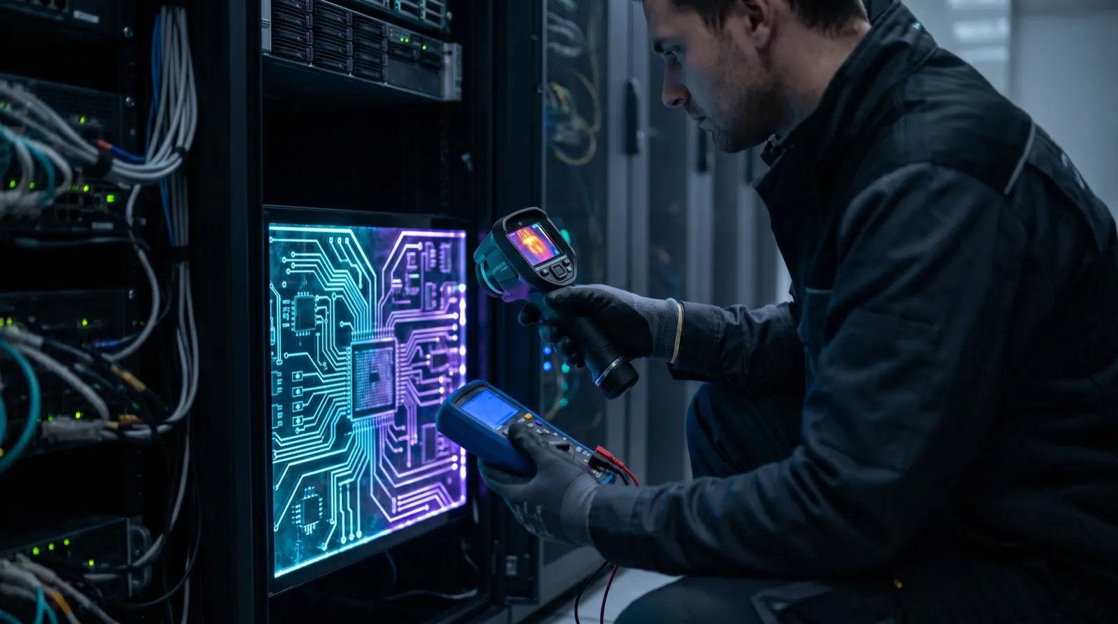
Thermal imaging is the single most powerful tool for finding faults that are invisible to the naked eye. A loose termination at a circuit breaker, a corroded neutral link, an overloaded conductor, or a failing connection in a junction box all generate excess heat before they fail catastrophically. Our FLIR thermal cameras detect temperature differentials as small as 0.05°C, allowing us to identify hot spots in energised switchboards, distribution boards, and cable trays without removing a single cover plate. Under AS/NZS 3000, all connections must be mechanically sound and electrically continuous; thermal imaging provides evidence of connections that are deteriorating toward non-compliance before they cause an outage or, worse, a fire.
- Insulation resistance (Megger) testing to AS/NZS 3000 minimums
- Thermal imaging of switchboards, distribution boards, and cable trays
- Earth loop impedance and prospective fault current measurement
- RCD trip-time and trip-current verification to AS/NZS 3017
- Voltage quality and harmonic distortion analysis
- Continuity testing of earth conductors and equipotential bonding
Tripping RCDs and Safety Switches
A tripping RCD is one of the most common fault calls we receive and also one of the most misdiagnosed. The RCD is doing exactly what it was designed to do — detecting a leakage current to earth and disconnecting within the 30 mA / 300 ms threshold mandated by AS/NZS 3000. The fault is not the RCD; the fault is whatever is causing the leakage current. Identifying which circuit is leaking, and then which section of that circuit, is a methodical process of load isolation and insulation resistance measurement. Our electricians will identify the leaking circuit without the need to replace the RCD, and will provide you with a clear diagnosis of the underlying cause — whether that is a failing appliance, degraded cable, moisture in a weatherproof outlet, or a wiring fault introduced during a previous renovation.
Diagnostic Reporting
Every fault-finding engagement concludes with a written diagnostic report. This document records the test equipment used, the test results obtained, the fault diagnosed, the root cause assessment, and our recommended remediation scope. Where we identify multiple issues during the diagnostic process — a common occurrence in installations that have been operating for many years — we categorise them by urgency: safety-critical items requiring immediate attention, maintenance items recommended within twelve months, and advisory items for longer-term planning. This report also serves as a valuable record for insurers, building managers, and strata committees, providing documented evidence of due diligence and professional assessment.
Frequently asked questions
Can you find the fault without tearing open the walls?
In most cases, yes. Thermal imaging, insulation resistance testing, and circuit isolation techniques allow us to localise faults to a specific section of cable or a specific connection point without destructive investigation. Where physical access is ultimately required — for example, to repair a damaged underground cable or replace a failed junction box — we will specify exactly where the access needs to be, minimising disruption to finishes.
My RCD keeps tripping but resets fine when nothing is plugged in. What does that mean?
This is a classic appliance-to-wiring boundary fault. When the circuit is unloaded, leakage to earth is low enough to not trigger the RCD. Under load, a degraded appliance or its supply cord leaks sufficient current to earth to trigger the 30 mA threshold. Our process isolates appliances one at a time while monitoring earth leakage current to identify the specific device, and we then inspect the circuit wiring to confirm no installation fault exists alongside the appliance issue.
How long does a fault-finding inspection take?
A straightforward fault on a single circuit — a dead outlet, a tripping breaker with an identifiable cause — typically takes one to two hours. Intermittent faults or faults that require thermal imaging of a large switchboard can take three to four hours. We provide a time estimate during booking based on the symptoms you describe, and we will always communicate clearly if the diagnostic process is taking longer than anticipated and explain why.
Do I get a written report after the fault-finding visit?
Yes. Every fault-finding engagement includes a written diagnostic report delivered the same day. The report documents test results, the fault identified, root cause analysis, and a prioritised list of recommended remediation work. This report is yours to keep and is useful for insurance purposes, body corporate records, and as a baseline for future electrical audits.