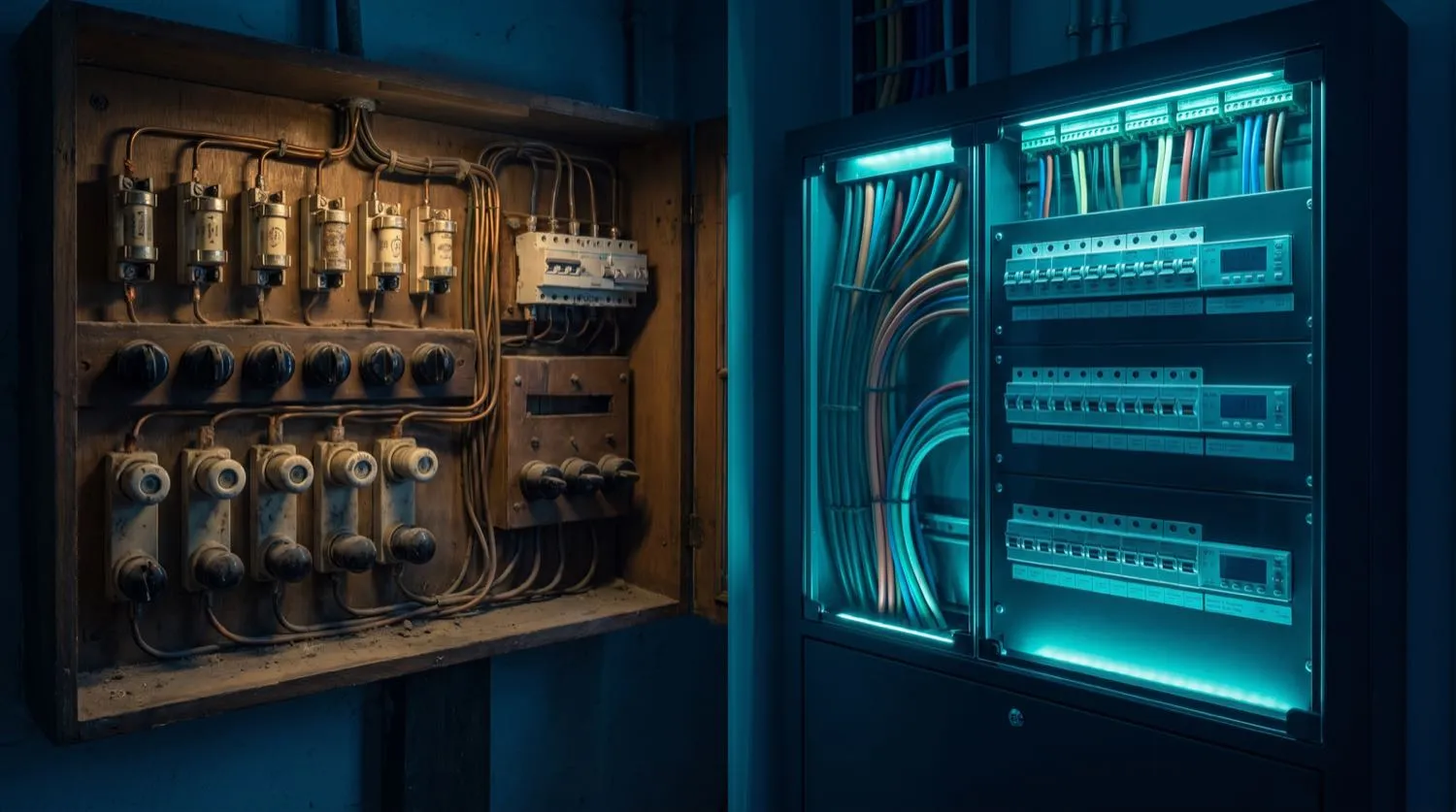
Walk into almost any residential or commercial building constructed before 1990 and the switchboard tells a story. Behind the metallic panel door, rows of porcelain or ceramic fuseheads hold rewirable fusewire — often a mismatched assortment of wire gauges, replacing the original specification fusewire with whatever the previous occupant had on hand. In some cases, the fusewire has been bridged entirely with a piece of copper wire or a nail, a dangerous practice that removes all overcurrent protection from the circuit. Even where the fusewire is correctly rated, a ceramic fuse offers no residual-current protection, no arc-fault sensing, and a clearing time that is orders of magnitude slower than a modern thermal-magnetic circuit breaker at overload currents. AS/NZS 3000:2018 does not permit new switchboards to be constructed with rewirable fuses, and state regulators across Australia regard legacy fuse switchboards as an elevated fire and safety risk requiring management.
The Technical Shortcomings of Rewirable Fuse Technology
Rewirable fuses are simple thermal devices: current heats the fusewire until it melts, opening the circuit. Their time-current characteristics, however, are poorly defined compared to modern devices. The clearing time is highly variable and depends on the ambient temperature inside the switchboard enclosure, the thermal mass of the fuse carrier, and whether the fusewire has been subjected to repeated near-tripping events that anneal and weaken it without full melting. A fuse rated at 20 A may pass 30 A for several minutes before clearing — more than enough time to overheat a 2.5 mm² cable that is rated for only 24 A in the same installation method. Modern thermal-magnetic circuit breakers, by contrast, have tightly controlled inverse time-current curves defined in AS/NZS 60898 (or IEC 60898-1), with the breaker guaranteed to trip within a defined window at a given multiple of rated current, from 1.13× (no trip) through to 10× rated current where instantaneous magnetic release ensures sub-cycle clearing.
- Rewirable fuses: clearing time at 1.5× rated current may exceed several minutes — cable damage is likely.
- Modern MCB (Type B, 10× magnetic release): clears in under 0.1 seconds at 10× rated current — cable protected.
- Type C breakers (instantaneous at 5–10× In): suited to motor and transformer loads with high inrush.
- Type D breakers (instantaneous at 10–20× In): industrial applications with very high starting currents.
- Fusewire replacement requires the circuit to be de-energised manually — MCBs and RCBOs reset in seconds without tools or spare components on hand.
What Is an RCBO and Why Is It Superior to Separate RCD + MCB Arrangements
A Residual Current Breaker with Overcurrent protection (RCBO) combines the thermal-magnetic tripping function of a standard miniature circuit breaker with the earth-leakage sensing of a residual-current device — in a single module that occupies one or two DIN-rail positions in the switchboard. This combination offers a critical advantage over the widely used arrangement of a single switchboard-mounted RCD protecting several downstream MCB circuits: selectivity. When a standard RCD protects eight circuits and one of those circuits develops an earth leakage fault at 2 a.m., all eight circuits lose power. In a commercial kitchen, a data centre, or a medical facility, this is operationally and potentially clinically unacceptable. With individual RCBOs per circuit, only the faulted circuit trips, and the fault location is immediately identified. The additional switchboard real estate and slightly higher per-device cost of RCBOs is generally recovered within the first nuisance-trip-free year of operation in any commercial environment.
- RCBOs provide both overcurrent (thermal-magnetic) and earth-leakage (30 mA) protection in one device.
- Individual circuit protection eliminates multi-circuit tripping from a single earth leakage fault.
- Selective co-ordination: in a fault, only the affected circuit disconnects — all others remain live.
- RCBOs are available in Type A and Type AC sensing, allowing correct selection for inverter and drive loads.
- AS/NZS 3000:2018 recognises RCBOs as compliant protective devices for both overcurrent and RCD functions simultaneously.
Prospective Fault Current and kA Ratings — a Hidden Switchboard Risk
One dimension of switchboard safety that is frequently overlooked in older buildings is the prospective short-circuit current (PSCC) at the switchboard busbars. Modern urban electricity networks deliver low source impedance — in some inner-city commercial premises, the PSCC can exceed 10 kA and in some cases approach 25 kA. A legacy fuse switchboard enclosure with a main isolation switch rated to interrupt only 3–4 kA of fault current is a structural liability: a bolted short circuit will cause a catastrophic, potentially explosive failure of the switchboard enclosure before the protection device can interrupt the fault arc. Modern Type-tested switchboards are assembled from components — enclosures, busbars, protective devices, and cabling — each rated to a common fault level, typically 10 kA for small commercial and 25 kA or higher for industrial distribution boards. Upgrading from a legacy fuse board to a modern compliant assembly is not merely a matter of adding RCDs; it means verifying the entire assembly against the actual available fault current at the supply point.
- Request the PSCC from the network distributor (e.g. Endeavour Energy, Jemena, United Energy, Ergon) before specifying protective devices.
- All devices in the switchboard — main switch, neutral links, busbars, MCBs, RCBOs — must be rated to at least the available fault current.
- The switchboard enclosure itself must be rated for the expected arc energy; IP ratings and Form of Separation (Form 2 through Form 4b) define bus and cable isolation levels in commercial installations.
- Short-circuit withstand (Icw) and conditional short-circuit current (Icc) ratings on busbars and enclosures must be verified in writing from the manufacturer.
- Cascade co-ordination ("back-up protection") using the let-through energy (I²t) of an upstream device to protect a lower-rated downstream device must be documented with manufacturer data.
The Upgrade Process: What to Expect
A switchboard upgrade in a residential context typically takes four to eight hours for an experienced team. The process begins with a load assessment to verify the existing cable sizes and confirm that the new protective devices are sized to the installed cable cross-sections — not merely to the historical fuse ratings. If the dwelling has solar panels, battery storage, or EV charging infrastructure, the upgrade must account for bidirectional current flow and the appropriate selection of generation protection per AS/NZS 4777. The network distributor is notified and the supply is temporarily disconnected at the service fuse. The legacy enclosure is removed, new DIN-rail components are installed and terminated, neutral and earth bars are verified against MEN requirements, and a full suite of verification tests is completed per AS/NZS 3000:2018 Chapter 8 before reconnection. A Certificate of Electrical Safety is issued referencing the standard, and the test results are attached. For commercial premises, a notice period to staff and a staged shutdown plan for critical loads are essential parts of the project scope.
- Load assessment first: confirm cable cross-sections match new device ratings before ordering switchboard components.
- Notify the electricity distributor at least two business days before supply disconnection.
- Verify MEN arrangement before and after the upgrade — do not assume the existing earthing is correctly configured.
- Complete and document all verification tests per AS/NZS 3000:2018 Chapter 8.
- Issue a Certificate of Electrical Safety covering all new work before energisation.
- For commercial premises, produce a shutdown plan and notify affected tenants or operations managers in writing.