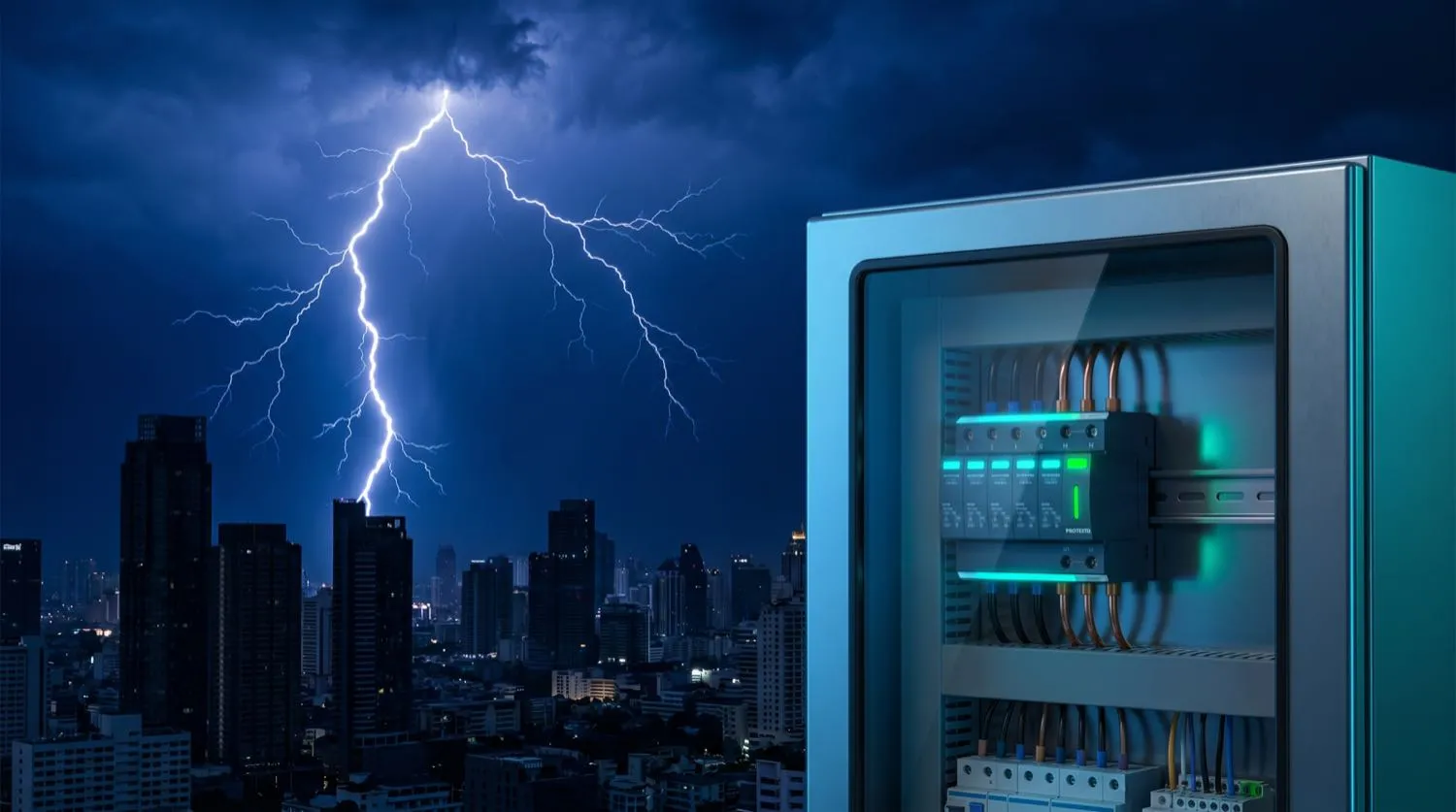
Modern commercial and residential buildings contain an extraordinary density of sensitive electronic equipment — programmable logic controllers, variable speed drives, medical diagnostic systems, networked AV infrastructure, building management systems, and data servers — all of which share a critical vulnerability: susceptibility to transient overvoltage events. A lightning strike does not need to hit a building directly to cause damage. An indirect strike within several kilometres induces a voltage transient on power, data, and telecommunication conductors that can reach thousands of volts for a few microseconds — far exceeding the 230 V or 400 V rating of connected equipment, and capable of destroying semiconductor junctions irreversibly. Switching transients generated by the disconnection of large inductive loads such as motors, transformers, and power factor correction banks generate transients on the same conductors, typically in the range of 2–4 kV. AS/NZS 1768:2007 (Lightning Protection) provides the Australian engineering framework for assessing lightning risk and designing coordinated protective systems, while AS/NZS 61643.11 governs the performance of surge protective devices (SPDs) installed in low-voltage power systems.
Understanding the Threat: Direct Strike, Conducted, and Induced Surges
The risk assessment methodology in AS/NZS 1768 requires the engineer to quantify the annual probability of damaging events based on the structure's location, dimensions, and local ground flash density (GFD) — expressed in flashes per square kilometre per year and obtained from the BoM lightning map. Australia's tropical north has some of the highest GFD values on the continent, with the Darwin region regularly exceeding 12–16 flashes/km²/year, compared with around 0.5–1.0 for temperate southern Australia. The standard then guides the practitioner through four categories of loss (human life, service loss, cultural heritage, economic value) and establishes tolerable risk thresholds against which the calculated annual risk is measured. If the calculated risk exceeds the tolerable limit, a protective system — air terminations, downconductors, earth termination network, and coordinated SPDs — is required.
- Direct strike: return stroke current (typically 30–200 kA peak) enters the structure directly — requires a lightning protection system (LPS) with air terminals, downconductors, and earth electrodes.
- Conducted surge: lightning energy enters via utility conductors (power, telecoms, data) from a nearby strike — mitigated by SPDs at the service entry point.
- Induced surge: electromagnetic field from a nearby channel induces voltages in internal loops — mitigated by bonding, shielding, and coordinated SPD placement.
- Switching transient: generated internally by motor starts, power factor correction capacitor switching, transformer energisation — mitigated by SPDs at switchboard and equipment level.
- Ground potential rise: a strike near earthing electrodes raises local earth potential, causing voltage differences between bonded and unbonded equipment.
Coordinated SPD Protection: Three Zones, Three Device Classes
AS/NZS 61643.11 and the application guidance in AS/NZS 1768 both advocate a coordinated, zone-based approach to SPD placement rather than a single device at the switchboard. The concept draws from the IEC 62305 series of lightning protection standards. Protection Zone 0 (outside the building envelope) is where direct and induced strikes occur with their full energy. Zone 1 is the interior of the building, where conducted surges arrive via utility services and equipment is partially protected by the building's shielding. Zone 2 and beyond describes the immediate equipment environment. A coordinated protection system places Type 1 SPDs (class I test, capable of withstanding the full lightning impulse current waveform 10/350 µs) at the main switchboard to absorb the bulk of incoming energy. Type 2 SPDs (class II test, 8/20 µs waveform) are placed at sub-boards and distribution boards to reduce residual voltage further. Type 3 SPDs (point-of-use, class III test) are fitted at final socket outlets serving sensitive equipment.
- Type 1 SPD at main switchboard: handles conducted lightning energy — must be certified for 10/350 µs impulse current (Iimp), typically 12.5–25 kA per pole.
- Type 2 SPD at sub-boards: limits residual voltage after Type 1 clamping — 8/20 µs waveform, rated by maximum discharge current (Imax) and nominal discharge current (In).
- Type 3 SPD at equipment: final-stage protection for servers, AV equipment, PLCs — installed within 10 m of the protected equipment.
- Voltage protection level (Up): the maximum clamping voltage the SPD allows through; must be below the equipment impulse withstand voltage (Uimp). For 230 V equipment, Up ≤ 2.5 kV is typical.
- Co-ordination between SPD types must be verified by the manufacturer — an uncoordinated combination can result in Type 2 SPDs absorbing energy they were not designed to handle.
Earth Termination Networks and Bonding — the Foundation of Surge Protection
An SPD is only as effective as the earth conductor it clamps surge energy into. The earth termination network — comprising earth electrodes, interconnecting copper conductors, and the bonding network linking all metallic services at their entry point — must present a sufficiently low impedance at the surge frequency (which extends into the hundreds of kilohertz range) for the SPD to clamp effectively. The DC resistance of the earth electrode, as measured by a fall-of-potential test, is only part of the picture; surge impedance is also influenced by the inductance of the conductor run between the SPD and the electrode. AS/NZS 1768 recommends keeping the combined length of SPD lead plus earth conductor to the earth bar below 0.5 m where possible, with conductor cross-sections of at least 6 mm² copper for Type 2 SPDs and 16 mm² for Type 1 SPDs connected to a direct lightning downconductor. Equipotential bonding at the service entry point — linking power, telecommunications, data, water, and gas services to a common earth reference — is the critical step that prevents destructive potential differences between services during a surge event.
- Earth electrode resistance: AS/NZS 1768 recommends below 10 ohms for most structures; below 1 ohm for structures with electronic systems requiring high integrity earthing.
- SPD earth conductor length: minimise to reduce surge inductance — keep combined lead + earth run below 500 mm for Type 2 SPDs.
- Equipotential bonding bar at service entry: connect all incoming metallic services (power earth, telecoms screen, data cable shield, water, gas) at a single point.
- Separation distance between lightning downconductors and internal wiring: AS/NZS 1768 provides formulae for minimum clearance to prevent side-flash arcing.
- Surge-referenced earth ring conductors around a building perimeter reduce ground potential rise effects on buried cables.
Maintenance and Replacement of Surge Protective Devices
A critical and frequently overlooked aspect of surge protection is that SPDs have a finite energy absorption capacity. Each surge event — whether from lightning or switching — consumes a portion of the device's cumulative rated energy (Wtot). An SPD that has absorbed several large surges may appear functional to a visual inspection but have a severely degraded clamping capability. Most quality SPDs include a status indicator (green/red window or LED) that signals when the device has reached end-of-life and must be replaced. Facilities maintenance programs should include annual visual inspection of all SPD status indicators, replacement of any device showing a fault indication, and after any severe storm event, inspection of all Type 1 devices serving buildings in a lightning-affected area. The cost of an SPD replacement is trivially small compared to the replacement cost of a server rack, a building management system controller, or a variable speed drive that the failed SPD was protecting.
- Inspect SPD status indicators annually and after every known severe lightning event in the area.
- Replace any SPD showing a red or fault indication immediately — do not assume it will continue to provide partial protection.
- Log SPD replacement dates and include SPDs in the building asset register with expected replacement intervals.
- After a confirmed direct strike event, replace all Type 1 and Type 2 SPDs in the affected switchboard regardless of status indicator state.
- Consult the SPD manufacturer for maximum discharge current capacity (Imax) to verify adequacy for the local GFD and connected equipment value.